
Almost all solar panels include integrated bypass diodes. Crystalline panels generally have three of them, which are located in the junction box and can each bypass a third of the panel when necessary. The diodes’ main task is to protect the solar cells from overheating when partial shading occurs. When combined with the right inverter, they can also help minimize yield losses on partially shaded roofs, as I’ve already mentioned a few times on this blog (may be not translated yet…). In this post, I’ll describe how to check whether all of a solar power generator’s bypass diodes are still in working order, which diode faults could occur, and how to correctly detect them. The first part of the post is about missing diodes; in the second part, I’ll discuss short-circuited bypass diodes. This post is intended for specialists and might not be suitable – or interesting – for anyone who doesn’t particularly care for technology stories.
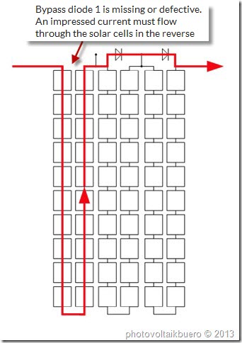
It’s not unheard of for a bypass diode in a solar power generator to be defective. Since bypass diodes only jump into action when a panel is shaded, defective ones tend to go undiscovered for a while. As I mentioned earlier, there are two types of problems that can befall a bypass diode, and they each present in different ways. In the first case, the bypass diode doesn’t conduct any electricity at all in either direction. This can occur if a diode was never installed, if the diode isn’t properly connected, or a strong current damaged the diode. In this case, the system operator wouldn’t notice anything at first. Only when the affected panel is shaded will the entire string’s current drop to that of the shaded cell; alternatively, the cell will even start consuming electricity if the inverter can reduce the voltage enough. If the bypass diode were working properly, it would only have to take on the voltage from the unshaded cells in its part of the string; as the negative voltage increased at the shaded cell, the bypass diode would become conductive. When the bypass diode is defective, however, it’s unable to intervene, and the cell receives more and more negative voltage until it eventually reaches a breaking point. When I say “breaking point” here, I’m not talking only about a mechanical malfunction, but also about the point on a diode’s curve when it also becomes conductive in the reverse direction. For some diodes (Zener diodes), this effect is used to achieve stable voltages in electronics circuits. For many others, though, the effect leads to damage because of the high power loss. Solar cells can withstand this breaking point for a short period of time, but they become so warm that damage can’t be ruled out over longer periods of time. The negative voltage that takes a solar cell to its breaking point is about 14 volts. Since 23 unshaded cells supply about 0.55 V * 23 = 12.77 V, more than 24 crystalline cells are never combined in a partial cell string. This way, a partially shaded cell can force the open-circuit voltage to the unshaded cells, thereby preventing too great of a current from flowing. If the bypass diode is working, that is…
To detect a defective bypass diode, you’ll need to send current through the solar power generator in the usual direction, preferably at night. Connect a power supply unit that will try to send electricity through the solar cells. Since the cells can’t supply power at night, the bypass diodes – if they’re working properly – will become active and guide the current past the solar cells. If a bypass diode is defective, no current will flow for the time being. Before conducting the test, you should know how many solar panels were connected in series in the string in question and how many bypass diodes each panel has. Multiply that number by 0.4 volts to find the amount of voltage that should cause the bypass diodes to become conductive. Above this voltage, the current should increase exponentially. If you conduct the test with our pvServe, set the current limit at about 50 percent of the nominal current for the panel being investigated.
For five-inch cells, for example, that level is about 2.5 amperes. Then, continue to increase the voltage until that current is reached. If you’re inspecting a string with 15 panels and each panel has three bypass diodes, then the diodes’ forward voltage is about 0.4 V * 15 * 3 = 18 V. The current should be reached when the voltage is slightly higher than that number. If no current is flowing, the cause is most likely a defective bypass diode.
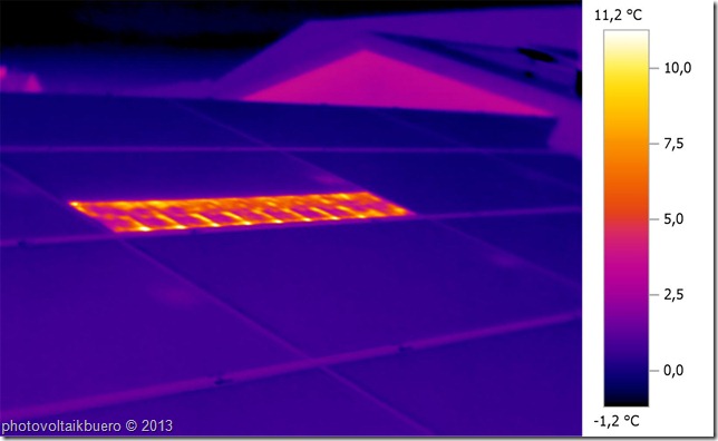
The next step is to find out which panel has the defective diode. For this, you’ll need much higher voltages – and a lot of careful attention. If only one diode is defective, then in the above example only 17.6 volts (instead of 18 volts) will be needed for the undamaged diodes. The current will have to flow backwards through the solar cells at the damaged diode. For 24 cells, the “breaking point” voltage is about 336 volts, which means that about 400 volts is needed for a current of 2.5 amperes. This current will heat up the affected cells relatively quickly, and the warmth will be visible with a thermographic camera. Since operating at their breaking point is very wearing on cells, make sure the test doesn’t take too much time. The difference in temperatures compared to the unheated panels is sufficient to quickly find the affected panel. If multiple diodes are defective in a string, things get a little more complicated, since the voltage always increases by about 340 volts (in the example above). pvServe can be used to detect up to three diodes in panel strings that aren’t too long (maximum voltage: 1,000 volts). If even more diodes are defective, your only option is to split up the string into multiple partial strings and inspect them separately.


Hi, i have a defective panel that shows 0 voc when measured.
The panel has 3 bypass diode.
Can i say i have 3 shorted diode?
I did test with multimeter with continuity mode..i got a beep sound showing short circuit when connected at the module connector
Hi,
there are two possible reasons for zero voltage:
1. 3 defective diodes (shorted)
2. a broken connection
If 2. would be true your multimeter wouldn’t beep, therefore it’s most likely case one.
Best regards
Matthias Diehl
Hi Matthias,
Thank you for your insight. Other than manufacturing problem, usually what causes the bypass diode to be shorted? Initially the string run normally than suddenly one day all of the module in the string does not producing any power..upon checking, all of the module have defective bypass diode (shorted). One abnormal that i found, one of the module connector are melting. Could the melting connector are the culprit? my hypothesis, once connector melt, the connector exposed to water ingression and cause a short spike of high current that would destroy the by pass diode.
Another question is, if all of this happen because of short and high current pulse, are the cell of the module are still ok?
Hello,
we observed several cases where nearly all bypassdiodes were damaged (shorted). In all cases this was because of overvoltage after a
lightning strike in the neighborhood. In most of these cases the inverters were also damaged.
There is a rule of thumb that overvoltage leads to shorted bypassdiodes whilst high current leads to open bypassdiodes.
Matthias Diehl
Interesting conversation.
I can confirm that we have seen lightning causing short circuited bypass diodes (due to high voltage).
What would be the cause of high current?
*A second lightning strike on already short-circuited bypass diodes?
*Or something else?
Does the cells get damaged with lightning strikes?
Difficult to say but my guess is, that an induced voltage could lead to such high currents (much higher than Isc).
Or a direct lightning strike…
Thank you for the feedback.
Does the cells get damaged with lightning strikes?
Hello Riaan,
it depends. When a direct strike hits a module the cell(s) are completely damaged. A lightning event in the neighbourhood may only lead to an overvoltage and shorted bypassdiodes.
We had several cases where the modules could be repaired, by changing the diodes.
best regards Matthias
Hi Matthias,
I suspect I have a missing diode in a module of a single string connected to a single inverter (I have 3 strings and 3 inverters in total). When at full sunlight nothing happens, but when a cell is partially shaded in that string, the power output is reduced by 90% roughly. Shading other cells of the other strings produce a drop in power but not even close to the first one.
I have a dc clamp meter and a thermographic camera to use… however I only have inspected the string without shading and every thing looked fine.
If I shade a cell on the problematic module I should see the current flow through the string drop to zero, because the missing diode won’t bypass the cell and this one will block the current, is this right?
If I do this on any other (healthy) module of the string the current won’t drop to zero (because the bypass diode will be active) but the voltage will be reduced by 1/3 of the module voltage?
Best,
José
Hi José,
you are absolutely right. A missing diode will lead to a significant drop of the outputpower, when the substring of the module where the bypassdiode is missing, is shaded. Whithout shading you will see no effect. When you shade a part of a module with healthy bypassdiodes and the inverter reduces the voltage by one third of the module-voltage, you should see the typical checkerboard pattern with your thermography-camera. I mention this, because not all inverters have a proper mpp-tracking. Some keep operating on local maxima instead of reducing the voltage and shift to the absolut maximum.
Nice to see, that our blog is even read in Uruquay 😉
Greetings to South America
Matthias Diehl
Thanks Matthias!
This site is by far the most in depth in PV evaluations I have found on internet. A great source of knoweldge!
Thanks,
José
Thank you very much
Hi sir Mathias,am writing to you from Kenya. Am really happy yo be connected to you through this forum. Recently it rained heavily and my 300watt solar panel stopped producing power. From this discussion, i may say maybe the diodes are a damaged. I have a 50A charge controller which is ok, can i remove the dameged diodes and depend only on the charge controller to control the reverse current?
Hi Samuel,
You have to differentiate between reverse current diodes and bypass diodes. Bypass diodes only help to bridge shaded substrings of a module while reverse current diodes protect reverse current to a module string. In most modern pv-systems there are no reverse current diodes. If you can open your junction box you can measure the voltage over each of the (most 3) bypass diodes. If these voltages are 0V, the diodes are shorted.
Best regards Matthias
Hi Matthias,
Can we say that if we have all of 3 bypass diode damaged (shorted) we still have no reduction of energy production if we do not have shade ?
If so what other problem can we have ?
Best regards
Nicola
Hi Nicola, when the bypassdiodes are shorted, the module is completely dead. It is true what you say for an open bypassdiode path.
If it remains undetected cells can be damaged when they are shaded because the power that is converted to heat in the cells is no longer limited.
Matthias Diehl
if bypass diode is damage due to high voltage. then what is my Voc and Isc of the damage bypass diode solar module ?
Voc is lowered by 1/3 of the modules voltage. Isc is the same.
Best regards
Matthias Diehl
I have a 150 watts module, and something wrong happened with its 9 diodes (lined in threes)..
I’m getting and approx 19.8 Voc and the Amperage is dropped to approx 3 (I should have 8, from what I know).
Is changing the 9 diodes going to fix this Solar Panel?
Please, help me.
to answer the question, additional information is needed. What cells 6″ or 5″ ? Number of cells ?
Module structure ?
Matthias, you have explained this thread very well & im very grateful for your simple yet concise explanation without going into some hectic scientific formulas etc. I am doing missions work in Zambia & were totally off the grid in rural Zambia. I run a 48v 4kva hybrid inverter with 4 x 255w panels. I’ve had issues with one of the batteries for a while now. I couldn’t afford to replace with exact battery withsame internal resistance & found out the hard way that one cannot replace a battery with any old battery! Anyway we’ve been limping along suffering the earlier switch off times until we can afford a better battery pack. However, of late we’ve had a lot of cloud cover and my inverter has been disconnecting the panels (even in full sun!). Yesterday I tested my four panels. Off load (open circuit) they test fine when the sun was weak & in full sun, but when connected I had one panel reading 1.5v and the other three ranged between 24v-18v each. I removed the “faulty panel” showing 1.5v and saw the three diodes you speak of but was totally flawed by the voltages I saw!! Open circuit I had 10v from each string which I now know to be normal, but on load was a whole different story!!! I’m going to do some more tests today thanks to this blog that has given me lots to think about!!! Just a shout out though for this blog!! Thank you!
Hi Darren,
thanks for writing from Africa. Nice to hear that the blog is read all over the world. If the voltage breaks down under load there can be two reasons:
defective cells or loose connections between the cells. Sometimes these effects are temerature dependent.
Greets to Zambia
Matthias
Hello Mathias, one of my solar panels was not giving more then 9v. So I took the diode out and now measure up to 3v? Just wondering wether to replace the diode or do a check first short circuiting the diode connection,
Or is my panel for some reason dead.?
Thanks rob
Hi Matthias,
If there are bad diodes in a panel, would this be evident from an initial assessment with a thermal camera? Do you expect a method like shading certain strings to be a viable method of testing diode function? Can you recommend any alternative methods (other than use of a thermal camera or physical inspection of the J-box)?
Thanks for your help.
Hello,
One of my friend running solar pump with 14 panels ..Suddenly the panels are showing only 50% of its nominal voltage ..
What could be the reason ..?
Does defective blocking diode in a single panel affects the whole string ….
Need your advice..
6 cell panels…
265watts ..
shorted bypassdiodes due to an overvoltage event can be the reason. It can also be caused by a high current of your pump.
Dear Matthias,
We put into power 300kW PV roof top plant, and one string on one inverter was showing 640V instead of 790V same strings on all 12, 25KW Fronius Eco inverter with 19 modules in series connected. When we open the string in the inverter there was a sparks occurring. We assume that we have at least three damaged modules in the string. Didn’t manage to check all the modules in the string. We leave the inverter powered on, everything is protected with gPV fuses, so the question goes. How long this string can operate if we have more than one damaged modules, are we in danger if the strings stay like this for a longer period before detecting the main problem? As I wrote above on the end of the solar cable there was a spark and the polarity of string “+” and “-” is connected properly this was double checked.
Thanks in advance for Your help.
BR.
Goran
Hello Goran,
you probably have several shorted bypass diodes. You should remove the 640V-string because it will no longer contribute to the energy yield. You’re seeing sparks because a current flows from the strings with the 790V to the string with the lower voltage. If you have no string fuses I strongly recomment to remove the string. It’s not very difficult to find the affected modules with a thermography camera.
Best regards Matthias pvBuero
very informative blog about solar panels. thanks for sharing this with all
great blog about solar panels.. thanks for sharing this with all..
Good Afternoon Matthias
thank you for this very informative detail I grasped most of what was said but would like to confirm something I have a 120w panel from a reputable brand that I am currently getting a full 17v from the panel when it is laying flat on the floor, BUT absolutely not a single watt or amp is being produced
could this also be due to a failed diode, I have since tested other panels small and large cheap units and they all getting power current and voltage so my means of testing is not flawed.
Please advise
Hello Gerard,
this is often the case when you have high resistive cell connctors. The connection is just good enough for some voltage, but when current flows the voltage drops to nearly zero.
Matthias Diehl
Thank you Matthias
the thing is there is full 17v but never any amps or watts. so the volts stays at around 17v even if connected to an MPPT controller but the battery never gets charged
may be a defective fuse in the input of the MPPT.
Matthias,
I work for a commercial solar company in SE USA. I fly drones for my company, performing thermal IR scans over all of our solar farms. One anomaly we often detect is that of lightning damage, where the thermal signature looks like the module is still performing, but has heat loss and cells that are obviously damaged. Most of the modules we use are polycrystalline with 3 diodes. Another similar anomaly we have identified looks the same, but looks to be “off”, with those same scattered “hot cell” signatures across the module. Oftentimes, we get to these and see that the j boxes have melted. Why might be there be a difference in these thermal anomalies we are seeing between lightning damaged modules and modules damaged by melted/faulty j-boxes? Is it accurate to identify either of these modules as “internally short-circuited modules”?
Hi Mateo,
what do you mean by “but has heat loss and cells that are obviously damaged”. How does the thermpgraphy image look like ? When I see lightning damage in most cases the Schottky Bypassdiodes are completely shorted (0 Ohms, but there are only sometimes some diodes which are melted. In these cases also the junction boxes show signs of heat. You need huge currents to melt a diode completely. We testet that in the lab. In conclusion I see shorted bypassdiodes and melted boxes often together. In some cases we found melted boxes due to a connection problem in the junction box. This was a serial error of the manufacturer concerned.
Matthias
Hi Matthias, a good piece, and also plenty in the blog, but not sure if it is my problem and maybe you can suggest something. I have 4 X 270w panels in series/parallel each with VOC : 38.4v and ISC: 9.21A. and a VMAX: 30.5 and IMAX of 8.8A. My VOC tested at 70v and 71v. The ISC of 6A and 6.5A. So within the tolerances suggested (ISC 20-30% of rated ISC?). But when I connect them to the mppt controller the voltage is about correct of around 65v but the currents from each series array one is well down e.g. 2.1A and 5.1A. These current readings are the outputs from each solar array when connected to the controller. This has an output from the mppt controller of only 260watts. Well below what one would expect at midday with no shade covering the panels in full sun. I have remade all connections thinking maybe a high resistance connection. I have yet to check under the terminal cover to test connections and diodes etc hoping to get all the possible tests required before accessing the underneath of the panels, so do it only the once. What would you suggest may be the issue when the VOC and ISC seem to test ok but when connected to the controller one of the array outputs is consistently half of the other identical array over barring times and cover during the day. Your advice would be greatly appreciated. Ian
Hi Ian,
that’s not easy to answer without knowing the whole system. What kind of Controller do you use ? With one or with two MPPT ?
If it’s only one MPPT and one of the two strings in parallel delivers only 2.1A when the other delivers 5.1A there is something wrong with the connectors or with the modules of the affected string. A thermography image would show us the situation at first glance.
That’s the way to go…
Best regards
Matthias
Evening Mathias.
I consist of a 5kva solar system for which the panels are located on my roof. I have 9 325W panels for which they are been set up in 3 pairs, meaning the 1st panel of each pair of 3, positive cable goes directly to my controller box then its negative connected to the second panel and second panel positive to third panel and then third panel negative then straight to the controller box. Just before the controller box each set of 3 panels positive and negative cables are been linked in order to create 1 positive and 1 negative cable. My question, lighting direct struck the middle set of panels for which my solar storage dropped from an average of 13kw/day to max 7kw/day. Is the problem with solar panels been damaged or a damaged charging controller in the inverter? My inverter doesn’t pull thru any faults on the LCD screen.
Greetings from Zambia
JZ
Hello Jacques,
greetings to Zambia,
it’s very likely that some bypassdiodes of your panels are damaged. You should measure the open circuit voltage of each solar-panel. Then you will find a voltage that is 0V 1/3 or 2/3 of the voltage of the panels which are still O.K. With a littly luck you can open the junctionboxes of the panels and change the damaged diodes. Unfortunately the diodes are sometimes potted with some potting compound.
Greetings from Germany
Matthias
Hello Matthias,
I have a system which consists of 32 230 watt panels with Enphase m215 microinverters. Last August, after a heavy rain storm, two of the panels produced only 2/3rds as much power as the other panels. After a few days, one of these two panels stopped producing any power at all. After about three months, the second one also stopped producing power. I contacted the manufacturer. Then wanted pictures of the insides of the junction boxes. In each of the junction boxes, one bypass diode was a brown color and the other two were black. My multimeter indicated that the brown diodes were not good. The manufacturer sent me new diodes to replace all three in each panel. I oriented one panel perpendicular to the sun’s rays and tested it. VOC was 33.5 volts and ISC was about 7 amps. I then re-installed the panels on the roof. One of them produced power just like all of the undamaged ones, but the other still did not produce any power. I rechecked the VOC (33.5) and ISC (2.6). It was cloudy and the working panels had been producing about 80 watts when I had turned the system off. The LED on the non-producing panel blinks green. I finally swapped microinverters but that panel still does not produca any power. What could be my problem? Why did the panels produce 2/3rds power for awhile and then die? Thank you much for your help. William
Hello William,
I recommend checking the modules with a thermography camera. Sometimes an overcurrent event causes high contact resistance on the the cells front or rear contacts. This loose contacts can get worse after some time. I even had cases, were these broken connections were temperature dependent.
Matthias
Hello Matthias,
This morning I swapped positions for two of the panels, putting the non-producing panel where one which was producing had been. The panel produces power there. The panel which I put where the non-producing one had been now does not produce any power. I’m now thinking that the socket where the microinverter plugs into the trunk cable may be where the problem is, but how do I check that socket out? Thanks again for your help. William
Hello Matt,
It’s Jim from Indonesia here. I have a string of 320Wp x 6pcs. But they only produced about 1/3 capacity. I disconnected each panels and measured the Isc = 8-9amps and Voc = 38V (which is congruent to the spex sheets). But when i connected all in series on my inverter, it produces 240V and ONLY 1.5A on average. Looking at the output graph.. they look like spikes (goes up to 3 then drops. Goes up to 2.. down.. sometimes goes up to 5 then plunges again)… rarely constant line even though the weather is bright summer. Could it be a busted diode? I couldn’t check because the jbox of panel is siliconed throughout. Thank you in advance.
Hi Jim,
seems to be a problem with your inverter. 240V is near to opencircuit voltage. It’s no wonder that there’s nearly no current.
Check if your inverter find’s the MPP (Maximum Power Point) voltage ?
Best regards
Matthias
Thank you Matthias, for you time and dedication to this resource feed of good information helping the PV community.
Currently I am working with a small micro scaled floating PV farm project that will utilize not only 3.1 KW PV array, but also wind, Drogue turbine, Tidal & Wave energy harvest with emergency diesel making a tru green hybrid..
Being refitted in the past 2 seasons our small sailing vessel has 16 sq.m of PV in two arrays, the 4 sq.m for refridgeration / W/ ships critical backup & then Primary Array of 12 sq.m
We had one panel, a Q4 – 345W @ 9.1A drive feeding a 200 Ah bank operating @ 24V and temporarily had placed a spacer cushion to support the panel from center with a 24″ x 24″ piece of soft material covered foam.
It was secured from 4 points one hinged to allow us to change angle while testing airflow over forward hatch and deck area for wind reaistance, as eventually we will hard mount it from the frame rails, testing in hurricane and squall or storm force 8+ winds & weather elements..
When we removed the cushon we noticed what looked like heat damage to the cussion cover? ? ? From what you have said here that might explain the heat source.. The back of the panel remains shiny white with no signs of anything, the 24V system seems fine, as it gets regular partial shade during each day cycle from ( cutter rig boom) directly over it a couple feet above..
But I am now curiouse to do some night time testing on a few panels.. Currently we have three seperate arrays, one 24V the one I mentioned feeding 216W into 200Ah bank.
A primary array of three panels in parallel with combiner box mid ship, two typically stowed beneath the upper one, we can lift the upper and pull one more or both the others out temporarily if needed or when we are on the hook (at anchor)
The third is aft, located atop the radar arch and dinghy davit arms.. Another single panel.. Experimental test panel..
Our center array, (mid ship) feeds a primary bank 300Ah @ 36V BUSS as three smaller 1KW inverters operate three separate AC and 12V sub systems all isolated consymption well ballanced.. Allowing us full harvest of full 345W capacity from each panel exposed to light as needed.. Etc..
I am working on the severe duty vector drive system for Regen under sail . project in development as we sail across the globe.
Thanks again for the information and shared thoughts..
Best regards,
Kim
I have a SW facing array on a flat roof in the northern U.S. (WI) that has inter-row shading. In the November, around 2 PM, the power drops precipitously, when a line of shade appears across the bottom few inches of the modules (72 cell modules, with 3 bypass diodes, mounted in landscape). I’m wondering if I have bypass diodes stuck in the open position. I’m wondering if I can troubleshoot during the day, since I don’t have a power supply using these methods? 1) If I cover a module, will the current drop significantly, if there is a bad bypass diode (significantly more than 10% if it’s in a string of 10)? 2) When the bottom edge is shaded, will that section show up as a hot spot in a thermal camera if the diode failed in the open position? Thank you!
If I cover a module, will the current drop significantly ? It depends on the MPPtracker of your inverter or charge-controller. will that section show up as a hot spot in a thermal camera ?
If the bypass diode is active you will see shaded cells getting increasingly warmer than the others.
Hello Matthias
I have a new system 5kW Sungrow Inverter with MPPT1 has 13 panels facing NW works fine and MPPT2 has 5 panels facing NE. My issue is the MMPT2 only produce current when in cloudy day, about 2 – 7 Amp and 170 Vdc, however when sunny day no cloud, the current is drop to zero and 220 Vdc. I have swapped the input of MPPT and the issue is moved. It seems to be inverter ok, but just need you option and help how to narrow the problem.
Thanks, and greeting from Sydney Australia
Hi Ben,
please check Vdcmin on the MPPTs of your inverter. Probably 5 modules in series is too less at high module temperatures.
Best regards Matthias
I have a 24 V home Solar setup with 24V 370W panels in parallel connected to a PWM based Solar Inverter/PCU.
Mono PERC Cells type Panel.
Capacity – 370W, 24V
Voltage: Voltage at Max Power (Vmax) – 39.25V, Open Circuit Voltage (Voc) – 47.08V
Current: Current at Max Power (imax) – 9.43A, Short Circuit Current (isc) – 10.01A
During early mornings and before sunset the output voltage reaches to high as 80V some times and solar inverter disconnects the Panel inputs.
During early mornings and early evenings there is tree shade in the site.
Is it due to faulty diodes?
Thanks in advance.
Sunil
If your open circuit voltage is 47,08V and you have only one module in series there cannot be a voltage of 80V. This is only possible when you connect two modules in series. You should check your cabeling.
Best regards Matthias
Matthias,
I have 4 ea solar panels that are supposed to produce 255 watt each (30 V x 8.5 A). As I attach each of the 4 panels (#1 to #4 below) to my grid tie power inverter, I measured the wattage produced with my Killa watt meter. The measurements were taken with clean panels in full sun on approx March 31, 2021., Below is the measurements
Panels Connected – Volts (AC) – Amps – Watts Produced / Added
#1 122.5v 1.43 175 (added +175 watt)
#1 , #2 122.5v 3.04 327 (added +152 watt)
#1, #2, # 3 122.7v 3.68 437 (added +110 watt)
#1,#2, #3, #4 122.7v 4.37 558 (added +121 watt)
The power of the 4 panels only hits approx. 558 watts total. The panels are supposed to be 1020 watts total new (they are about 5-7 years old now). I know that people never get the power panels are “supposed” to produce due to the Standard Test Procedures used. But what do you think about the power output based on your experience? Do you think something may be wrong with panels 2-3-4 based on the power they added to the grid tie inverter power production? To me the power seems low. I was thinking about replacing the diodes. Do you think this may help to fix anything?
The power on type label is always measured under STC (1000W/m², 25°C, AM1,5). That are conditions you ‘ll never have in the field. In most cases the modules are a lot warmer than 25°C when they see an irradiation of 1000W/m². Even if everything is perfect with your modules, they can only deliver the maximum power, when you operate them in MPP (maximum power point).
Therefore it’s not easy to check the real power of solarmodules without sophisticated devices as iv-curve tracers. In a first attempt I would measure the short circuit current and the open circuit voltage of all modules simultaneously. Under the same irradiation and the same temperature all 4 modules should deliver the same results. If that’s not the case, it is a first hint to a problem on one of the modules.
If you have an iv-curve tracer… this would be the way to go.
Best regards Matthias
BTW I tried to make a chart to show power produced on my previous message sent, But the format got messed up during the process. I will write it down manually (below). Hopefully this comes out better but I won’t know until after I hit the submit button… Sorry…………………………………………………………………………
#1 solar panel connected, 122.5v, 1.43 amps produced, 175 watts produced (added +175 watt)……………..
#1 #2 solar panels connected, 122.5v, 3.04 amps produced, 327 watts produced, (added +152 watts)……….. #1, #2, # 3 solar panel connected, 122.7v, 3.68 amps produced, 437 watts produced, (added +110 watts)….. #1,#2, #3, #4. solar panel connected, 122.7v, 4.37 amps produced, 558 watts produced, (added +121 watt)..
Hi Stephen,
I’m quite sure you did not have an irradiation of 1000W/m² and 25°C module temperature (STC).
In addition, the inverter may not have good MPP tracking.
Best regards Matthias
Hi Matthias,
is is a great ressource of information, thanks for all the responses. I have a 3KW installation on my roof in Bordeaux consisting of 25 panels a 120W, 18V each organized in 2 parallel strings. Unfortunately the inverter shows only shows only a max of 150V in each string instead of >200V at noon with MPPT (arount 7Amp) and an Voc of 208V instead of at least 21*12=250V so I suspect a short circuit in some bypass diodes. Strange enough I have nearly identical values on both strings where the current is about 10% lower on string 2 but I expected moreover different voltages due to the uneven panel distribution but same current values. What do you suggest as a diagnostic method ideally without unmouting all panels ? Thanks in advance for taking your time
Rainer
Hi Rainer,
the first thing to do in such cases is a thermography. If you do it with a drone, it takes 5 minutes and you know what’s wrong.
You ‘ll easily find shorted bypass diodes or open cell connectors which are both responsible for lower voltage.
Matthias
OK, thanks Matthias, I’ll look out for a thermography service. Do I understand it right that I should look during a day with strong sunlight for temperature differences where a shorted bypass diode creates slightly higher temperatures as the respected cells don’t deduct electric power ?
Rainer
please read this:
https://photovoltaikbuero.de/en/pv-know-how-blog-en/finding-shorted-bypass-diodes-in-photovoltaic-systems/
Hello Matthias!
Thanks for the article, thanks to it, it seems I am close to the the end of my search for logical reason, that I thought might be behind this next thermographical video.
If I may just ask you to take a look: https://www.dropbox.com/s/pt5tj1wwz63dqrs/temp%202.MP4?dl=0
And may I just ask:
1. Is that the same problem that is discussed in this article – there are 3 bypass diodes shorted (1 on each of the 3 panels)?
2. This installation is half a year old (installed on Oct 2020) and now lightning storms have occurred so far, so what might have caused it (what to try to prevent in the future)?
3. How fast should I repair the diodes to prevent the rest of the panel from getting damaged?
Thank you very much!
1. Is that the same problem that is discussed in this article – there are 3 bypass diodes shorted (1 on each of the 3 panels)?
No, if the bypass diodes were shorted you would see the typical pattern with warmer and colder cells. The temperature of the cells on the affected modules is evenly distributed and it is a little higher than the temperature of the other modules. That means on these three modules one third is in open circuit.
This is due to an interrupted cell connector between two cells of the substring or between the junction-box and the first cell of the substring. In the last case you have a chance to repair the 3 modules. In the first case, the problem lies in the module and cannot be repaired. Take a look at this article: https://photovoltaikbuero.de/en/pv-know-how-blog-en/creeping-losses-in-the-output-of-photovoltaic-installations/
Best regards Matthias
Hello Matthias,
Few days back I came to know a very interesting issue in the field. The plant operation was started few days back only and in one of the SCB, team found damage to the Fuses. The fuse holders were melted. On further, analyzing the same person reported that all the modules of 5 strings out of 14 have no open circuit voltage. On checking it was found that all the three diodes are short. Now as a thumb rule we say the short diode are due to high voltage. I am not able to understand the reason for this. This happened in sunny day light and also there was no lightning in near by area in previous night.
Regard
Nikhil
Hi Nikhil,
I know of cases with many shorted bypass diodes only due to overvoltage in most cases due to lightning.
Another possibility is that a large amount of current is fed back from the inverter. In these cases, however, the inverter is unlikely to survive.
Matthias
Dear Matthias I have a panel giving me good voltage but 1/4 amperage on load. Can this be bypass diodes problem? Thks.
Great details and definitely handy if you have the capabilities to back power your string of panels and have a thermal camera. I’m in the other case and what’s worst, I’ve already broken some panel mounts trying to get panels off to test. I’m wondering if a large sheet of cardboard could be used to determine which panels have open diodes?
My thought is to look at the overall system voltage(either with a DVM or monitoring the inverter reporting which is roughly every 15 seconds when all panels are in the sun, then one by one cover a panel and watch the overall panel voltage drop and maybe watch the current too. If I cover a panel with any failed diodes, wouldn’t there be a significant drop while panels with functioning diodes will drop system voltage by one panel(+3 diode drops) and current drop by the panel power rating/voltage dropped?
My string is of 13 Sharp 165W panels. Thanks.
Hi Doug,
you can do that with a cardboard. One small correction: When you cover a modules substring where the bypass diode is open, the current of this string will completely go to zero because the shaded cells cannot be bypassed any longer.
Best regards Matthias
Great, so I should see a similar voltage drop for each panel unless a panel is not performing like the others and if I see no current then we know there’s one or more bypass diodes failed. I will give this a try. Thanks!
Thanx Matthias for the great information. I have a 120W solar panel that produces upto 20V in full direct sunlight but only produces a maximum of 2.5 Amps and yet earlier it could produce up to 7Amps. I have tried changing all the three bypass diodes but nothing seems to change. What could be the problem?
Dear Hussein,
sorry but I cannot answer this question without further information of the module.It can be defective cells, defective contacts …
There are a lot of possibilites.
Matthias
Matthias,
Lots of really great information… is it possible you cam help me too?
https://photos.app.goo.gl/FsdgrkuJPPuAwkhD6
This picture shows what happens on the input channels to one of my inverters on a hot hazy clear sky day.
The inverter is 6.0kw rated and at the peak input channel 1 is producing about 3500w whilst channel 2 is at its trough at about 300w as the afternoon progresses they slowly even out.
What is happening here please ?
There is no hard shading and both strings are equal.. 14 x 370w panels voc 40.8 is 11.54.
On a less hot and hazy day the channels match up almost perfectly… just seems to be on the super fine days.
Have I got a damaged panel and what is an east way for me to locate it if so? Without expensive imaging or curve testing gear 🙂
Appreciate any advice greatly
Thank you
Rich
Hi, it’s quite obvious that the inverter is derating (limits the output power). The question is why ?
It can only be answered when I have more information about the inverter. Does it have 3 MPPT ?
Is there a limit of a maximum current for each channel ?
Hello,
Hallo,
ich habe ein Problem mit einer PV-Anlage (sunways STH-10KTL-HT 2xString, 9 Solarmodule Voc 330VDC und 11 Solarmodule Voc 410VDC.) Der String 9SP ist werkseitig abgeklemmt. Auch das Vertauschen der Strings am Wechselrichter hilft nicht weiter.
Der Ausfall ist nicht von der Beleuchtung abhängig, sondern tritt zufällig auf.
Interessanterweise wird die Spannung des Strings immer noch vom Wechselrichter erkannt, aber die Produktion ist gleich Null. Könnten Sie mir helfen, dieses Problem zu lösen, oder mir zumindest sagen, wo ich das Problem suchen muss?
Vielen Dank, mit freundlichen Grüßen Lubos Paldus.
das lässt sich aus der Ferne leider nicht ohne weiteres diagnostizieren.
Hi Matthias,
How would you evaluate these thermal images. In my opinion, the module in the top has some bypass issues. Also below. But what could be a reason for that. It’s installed on the roof, it’s difficult to believe that lightning could strike.
https://drive.google.com/drive/folders/1iBUiZ5QeikRuRk5mYtye-DFJTmw4qUGH?usp=sharing
Hi Jonas,
you see these pictures when some cells become energy consumers while others are still producing. This can be due to dirt on the cells and a good MPP tracker on the inverter, but it can also be shorted bypass diodes. To be 100% sure, you need to fly a second time with the inverter turned off during one flight. If the pattern stays at the same position, you can be 100% sure that the corresponding bypass diodes are damaged.